 SMART Scan+
 SMART 3D-Scan
 SMART Full Body
 SMART Single+
 SMART Multi-Fiber
 SMART 3D-Fiber
 SMART DAQ
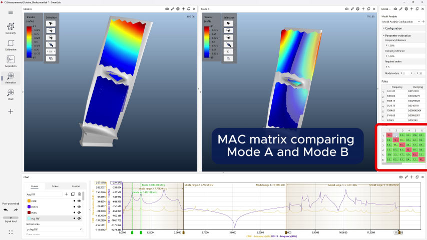
 Software SMART Lab
 Scanning Vibrometer
 Vector-Series
 Vector-Micro-Optics
 Nova-Series
 Nova-Xtra
 Fiber-Series
 Fiber-Multiplex
 Fiber Micro Manipulator
 OptoSCAN
 OptoGUI
 Single-Point Vibrometers
 Scanning Vibrometers
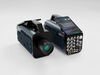
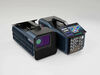
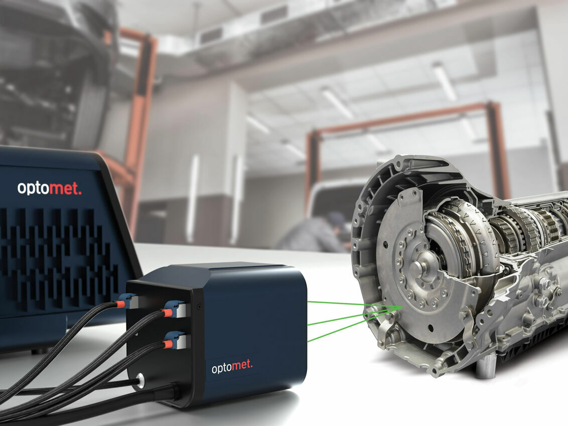
 3D-Laser Vibrometers
 Acoustics & Ultrasonics
 Aerospace and aviation
 Automotive
 Biology & Medicine
 Brake noise
 Civil Engineering
 Electronics & Household Devices
 Materials Research
 Medical technology
 Tools & Machinery
 Turbine
 Wind tunnel testing

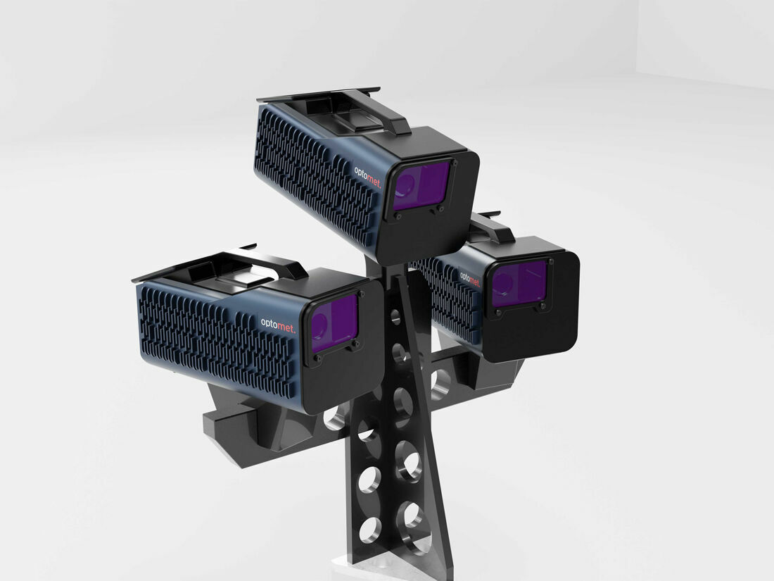
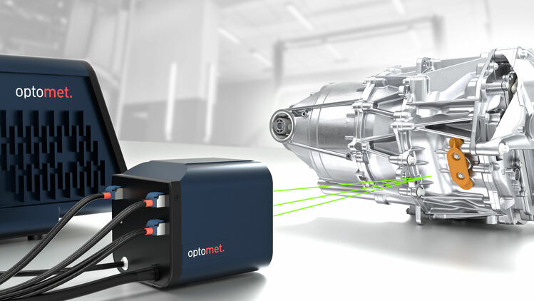
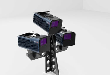
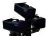
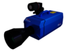
A 3D laser vibrometer captures vibrations in all three spatial directions at a single measurement point. To achieve this, three laser beams measure the same point from different angles. The measured vibration components – initially recorded in the respective beam directions as u, v, and w components – are then transformed into a Cartesian coordinate system (x, y, z).
There are two basic types of 3D laser vibrometers: The 3D single-point vibrometer measures the three-dimensional vibration at a fixed measurement point. The 3D scanning vibrometer additionally captures many points automatically in sequence and provides complete 3D mode shapes across an entire measurement surface.