
Application report
Identifying In-Plane Modes in Brake Discs with 3D Scanning Vibrometry

Brake squeal is usually driven by the coupling of an out-of-plane disc mode with an in-plane mode, often only a few tens of hertz apart: microphones and single-axis sensors see one merged peak. 3D scanning vibrometry measures the full vibration vector at every grid point, separates axial, radial and tangential components and allows each mode to be classified unambiguously.
According to the European Commission, Euro 7 is the first emission standard to also limit particles from brakes. Discs, pads and coatings are changing faster than experience with Noise, Vibration and Harshness (NVH)—that is, noise, vibration and harshness—can keep up. Reliable in-plane mode identification is therefore becoming a prerequisite for releasing new friction pairings without new squeal problems.
Euro 7 Is Changing Discs, Pads and Coatings
According to the European Commission, Euro 7 is the first emission standard to also limit particles from brakes. It applies to new types of passenger cars and light commercial vehicles from 29 November 2026 and to new vehicles of these categories from 29 November 2027.
The main levers are new friction formulations, coated grey-cast-iron discs and new disc materials. All of these change stiffness, damping and friction coupling in the brake system.
Squeal countermeasures can therefore no longer be tuned by trial and error. Engineers need to know exactly which disc modes are involved. This includes the in-plane modes that conventional test methods tend to miss.
Why In-Plane Modes in Brake Discs Matter for Squeal
A brake disc has three families of modes. High-frequency squeal usually involves at least two of them. Each family is labelled by its number of nodal diameters (n) and, for bending modes, its number of nodal circles (m).
| Dominant motion | How it is excited | Typical role in squeal | |
|---|---|---|---|
| Out-of-plane (OOP), bending mode | Axial, normal to the friction surface | Pad normal force fluctuations | Radiates sound efficiently and is the audible partner |
| In-plane tangential (IPT), tangential in-plane mode | Along the circumference, in the disc plane | Directly by the friction force | Pumps energy into the system and is often the driving partner |
| In-plane radial (IPR), radial in-plane mode | Radially, in the disc plane | Indirectly, via pad geometry and coupling with the disc hat | Can shift in frequency or couple with neighbouring modes |
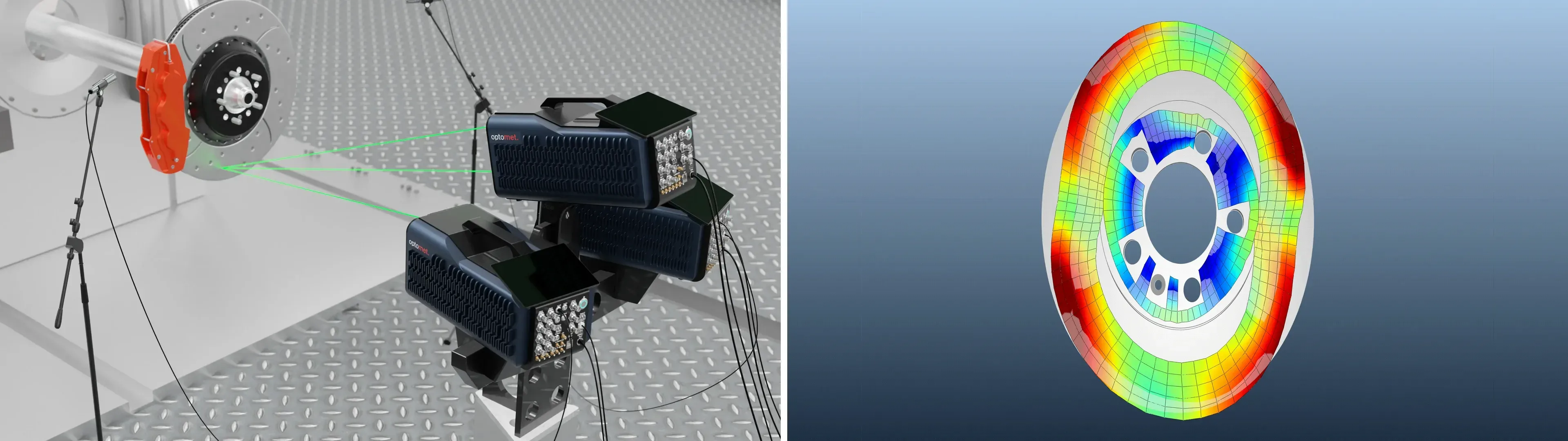
The following animations each show one mode from the three mode families. They were generated from the measured frequency response functions (FRF).
Out-of-plane
2.626 Hz
In-plane radial
5.989 Hz
In-plane tangential
12.448 Hz
Mode coupling as a cause
The critical mechanism is mode coupling. Under friction, an OOP mode and an in-plane mode with the same nodal diameter count can merge in frequency and become unstable. This is a classic cause of high-frequency squeal.
The in-plane partner is rarely visible in the noise spectrum, yet it is the mode the countermeasure has to address.
Why in-plane modes are hard to find
- Closely spaced frequencies: In passenger-car discs, in-plane and OOP modes of similar order often lie only a few tens of hertz apart, sometimes less.
- Additional axial motion: The hat is offset from the friction ring. As a result, in-plane modes also produce axial motion on the friction surface and look like just another bending mode in a single-axis measurement.
- Doublets: Every mode with n > 0 exists as a pair with the same mode shape. Vanes, drilled holes and material inhomogeneity split these pairs by a few hertz, multiplying the number of closely spaced peaks.
Why conventional sensors fall short
When two modes lie within each other's bandwidth, it is hard to separate them with a spectrum alone. However, they can be distinguished by the direction and spatial pattern of the motion. Conventional sensors deliver neither in full.
| What it sees | Limitation for in-plane modes | |
|---|---|---|
| Microphone | Radiated sound pressure at one position | Dominated by OOP radiation; in-plane modes radiate weakly. No spatial or directional information, so a merged peak cannot be split. |
| Accelerometer, uniaxial or triaxial | Acceleration at a few points | Added mass of a few grams shifts disc frequencies and adds damping. Few measurement points cannot resolve doublets or high nodal diameter counts. Not usable on a rotating disc without telemetry. |
| Single-axis scanning laser Doppler vibrometer (SLDV) | Velocity along the laser beam | Contact-free measurement with a dense grid, but measures one projection only. At normal incidence it sees axial motion. In-plane modes appear only through their axial side effect and are easily mistaken for bending modes. |
Squealing events add a second problem: they are short and not repeatable. A short time record limits the frequency resolution. Closely spaced modes therefore cannot be separated reliably from the spectrum alone.
The reliable way out is to measure what distinguishes the modes physically: the three-dimensional vibration vector at every point of the disc.
The measurement principle of 3D scanning laser Doppler vibrometry
A 3D scanning vibrometer points three synchronized laser beams from different directions at the same spot. Each beam measures the projection of the local velocity vector onto its own axis. Combining the three measurements gives the full vector — without touching the disc.
The natural reference for a brake disc is its axis. Expressing the vector at each point relative to this axis yields the three quantities needed to classify disc modes:
- Axial: Out-of-plane bending motion.
- Radial: In-plane motion towards or away from the axis.
- Tangential: In-plane motion along the circumference.
Measurement procedure on a stationary brake disc
A complete in-plane mode survey of a passenger-car brake disc takes one measurement session on a stationary disc, followed by targeted checks on the assembled corner or the brake dynamometer.
Mount the disc
The disc is mounted free-free using a soft suspension, or on the hub.
Import a CAD or FE mesh
The measurement grid is generated in SMART Lab directly from the imported CAD or FE geometry.
3D calibration
The three measurement heads are automatically calibrated in three dimensions.
Excitation and scan
For the scan, the disc is excited tangentially or obliquely at the outer rim using a shaker or impact hammer.
Transformation from UVW to XYZ
The three velocities measured along the beam directions of the three measurement heads (UVW) are transformed into Cartesian coordinates (XYZ).
Identify modes and correlate them with the FE model
For each peak, the response maps are compared, the nodal diameters counted and the modes correlated with the FE mode shapes.
Six points for capturing in-plane modes
- Boundary condition
- Start free-free with a soft suspension to get clean disc modes for FE correlation, then repeat the measurement on the hub or in the assembled corner to see how mounting shifts and splits them.
- Excitation direction
- Axial excitation barely drives in-plane modes. Excite the disc tangentially or obliquely at the outer rim, with a shaker or impact hammer, so that all three mode families respond.
- Grid density
- Place enough points around the circumference to resolve the highest nodal diameter count of interest. Include the outer rim, where radial motion can be seen directly.
- Frequency range and resolution
- Cover the full squeal range. Choose a frequency resolution fine enough that split doublets and closely spaced OOP/in-plane mode pairs appear as separate peaks.
- Beam geometry
- Position the three heads at wide angles to the disc normal. The in-plane components are derived from the oblique beams, so wider angles give cleaner in-plane results.
- Analysis
- For each peak, compare the axial, radial and tangential response maps. Count the nodal diameters and correlate the modes with the FE mode shapes.
What a 3D scan reveals about a brake disc
The decisive output of a 3D scan is how the motion of each mode is split between the axial, radial and tangential directions. On a typical vented passenger-car disc, this reveals three situations that a spectrum alone cannot resolve:
- Hidden coupling pairs: Where the spectrum shows a single broad peak, the 3D data often reveals two modes: an out-of-plane bending mode and an in-plane tangential mode with the same number of nodal diameters. This is the textbook pair for mode-coupling squeal. The countermeasure has to address the in-plane partner.
- In-plane modes that look like bending modes: Because the hat is offset from the friction ring, in-plane modes also show clear axial motion. In a single-axis measurement they look like just another bending mode. Only the dominant in-plane component reveals what they really are.
- Split doublets: Two modes with the same shape but slightly different frequencies show up as separate peaks. Their spacing is a direct indicator of disc asymmetry, useful for checking vane patterns or casting variation.
What mode identification changes in development
Knowing the in-plane partner of a squeal mode turns countermeasure design from trial and error into targeted engineering.
| Without 3D identification | With 3D identification | |
|---|---|---|
| FE model validation | Only bending modes are correlated; in-plane modes remain unchecked. | All three mode families are correlated using the Modal Assurance Criterion (MAC), which assesses the agreement between mode shapes, including doublet splitting. |
| Squeal countermeasures | Shims, chamfers and damping are tried on the audible mode. | Geometry or material changes aim to separate the actual coupled mode pair. |
| Euro 7 friction pairings | Each new coating or pad compound needs a full noise matrix to find problems. | The modal shift of disc variants is measured and compared before dynamometer runs. |
| Disc variants and suppliers | Differences are found late, as warranty cases. | Doublet spacing and in-plane frequencies serve as quality metrics. |
The largest gain comes early in the Euro 7 development programme. When a low-emission coating or a new disc material is introduced, a 3D scan of the old and new disc shows within one day, whether an in-plane mode has moved towards a neighbouring bending mode. That risk can be designed out before the first noise matrix on the brake dynamometer.
Recommended systems for brake disc measurements
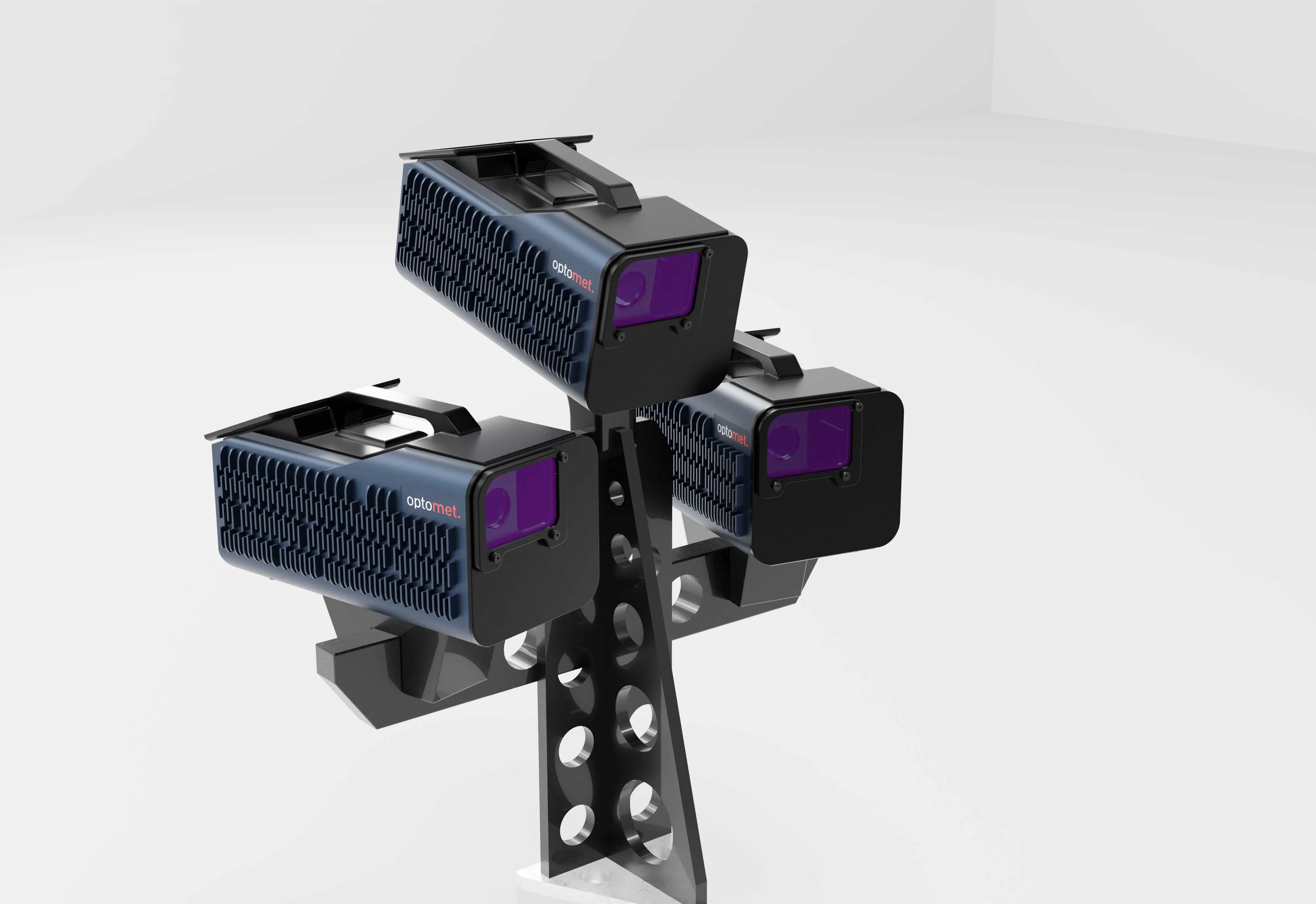
SMART 3D-Scan
SMART 3D-Scan with the SMART Lab modal analysis option for full in-plane mode identification and FE correlation.
View product
SMART Scan+
SMART Scan+ enables fast single-head scans where only bending modes are needed.
View product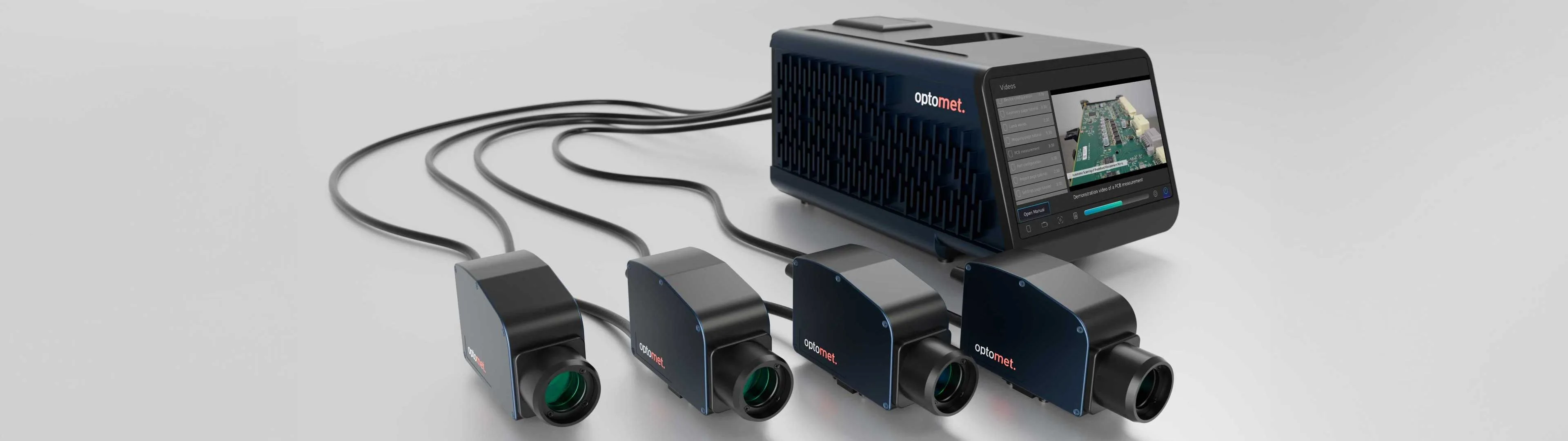
SMART Multi-Fiber
SMART Multi-Fiber or SMART 3D-Fiber captures all points simultaneously in the same squeal event.
View productSources and references
For brake emissions, Euro 7 refers to the test procedure under UN Regulation No. 179 (UN R179), the further development of UN GTR No. 24 (UN Global Technical Regulation No. 24). This transition is introduced by Delegated Regulation (EU) 2026/1214, in force since 23 September 2026.
- Regulation (EU) 2024/1257 (Euro 7) on EUR-Lex
- HELLA: How the Euro 7 emission standard challenges brake manufacturers. The article describes the limits for brake particles with a diameter of less than 10 micrometres (PM10) and the GTR 24 test procedure as it stood before the transition to UN R179.
References
Kinkaid, N. M., O'Reilly, O. M., Papadopoulos, P.: Automotive disc brake squeal. Journal of Sound and Vibration 267(1), 105–166 (2003). Overview of squeal mechanisms, including mode coupling.
Chen, F., Tan, C. A., Quaglia, R. L. (eds.): Disc Brake Squeal: Mechanism, Analysis, Evaluation, and Reduction/Prevention. SAE International, 2006.