 SMART Scan+
 SMART 3D-Scan
 SMART Full Body
 SMART Single+
 SMART Multi-Fiber
 SMART 3D-Fiber
 SMART DAQ
 Software SMART Lab
 Scanning Vibrometer
 Vector-Series
 Vector-Micro-Optics
 Nova-Series
 Nova-Xtra
 Fiber-Series
 Fiber-Multiplex
 Fiber Micro Manipulator
 OptoSCAN
 OptoGUI
 Single-Point Vibrometers
 Scanning Vibrometers
 3D-Laser Vibrometers
 Acoustics & Ultrasonics
 Aerospace and aviation
 Automotive
 Biology & Medicine
 Brake noise
 Civil Engineering
 Electronics & Household Devices
 Materials Research
 Medical technology
 Tools & Machinery
 Turbine
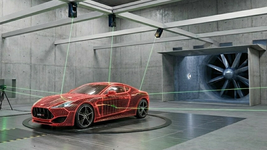
 Wind tunnel testing
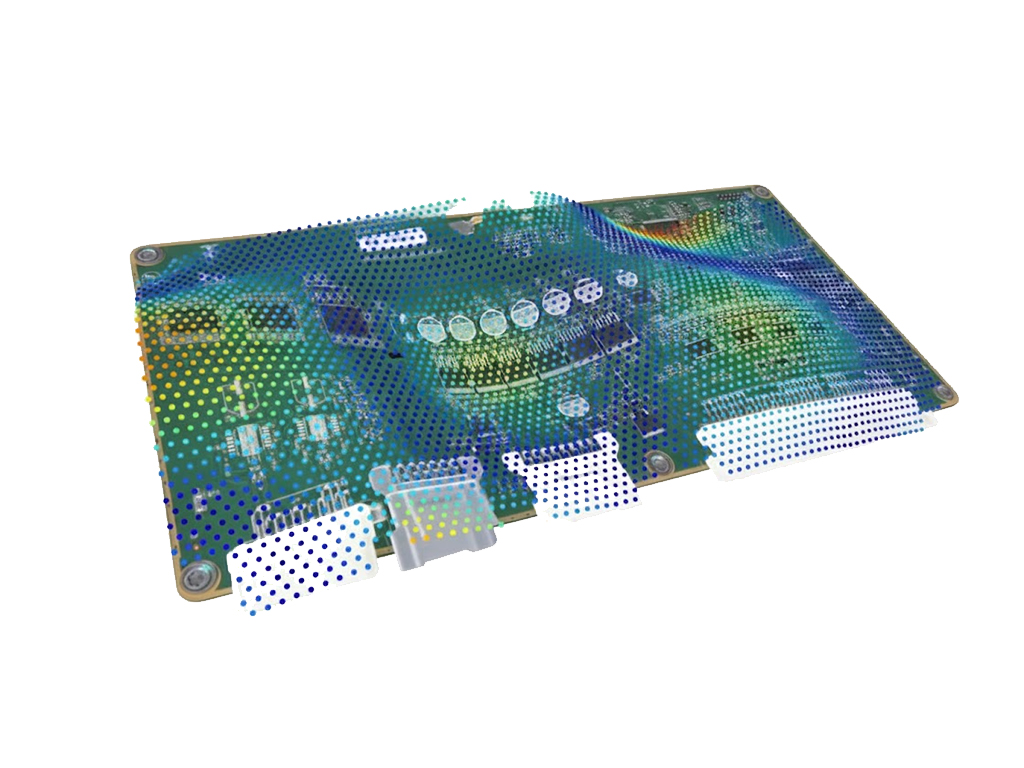
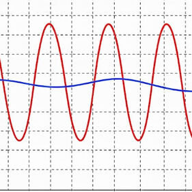
A scanning laser vibrometer measures vibrations non-contact and sequentially at many points of a test object. For this purpose, the laser beam is automatically guided across a defined measurement grid. At each point, velocity, displacement, and acceleration are recorded. This creates a complete representation of the vibration shapes of a component – from local resonances to global modes.
- Products
- Applications
- Knowledge
- Optomet
Optomet GmbH
Uhlandstraße 9
64297 Darmstadt
Mail:
sales(at)optomet.de
Phone: +49 6151 38432-0

What is a laser-scanning vibrometer?
Laser-scanning vibrometers are used when the spatial distribution of vibrations is relevant, for example in modal analysis, NVH investigations, or when validating numerical models. Because the measurement is purely optical, the test object remains unaffected. No additional mass is applied, as would be the case with accelerometers or other contact sensors. The natural frequencies of the system remain fully preserved.
The measurement works independently of the surface properties and can also be performed on very hot components, for example on heat-loaded engine and drivetrain parts on the test bench.
Comparison: Scanning vs. Single-Point Vibrometers
 |  | |
|---|---|---|
| Measurement principle | Automatic scanning of an area with many measurement points to generate a complete vibration shape. | Measures the vibration at a defined point along the laser axis. |
| Positioning | No repositioning required – the laser beam is guided across the measurement field via integrated deflection mirrors. | Repositioning required when another point needs to be measured. Alternatively possible using multiple single-point vibrometers or fiber heads. |
| Spatial information | 2D or 3D information depending on system configuration. | 1D information (velocity, displacement, acceleration along a single axis). |
| Typical applications | Full-field vibration analysis, modal analysis, and investigation of complex structures. | Single-point measurements on machines, tools, structures, or components in quality inspection. |
Procedure of a measurement with a laser-scanning vibrometer
In a laser-scanning vibrometer measurement, the laser beam is not directed at a single point but is guided sequentially to many defined positions on the surface. The Doppler shift of the reflected light caused by the motion is evaluated for each measurement point in the integrated interferometer. This produces complete data sets of velocity, displacement, and acceleration – non-contact, without additional mass, and with precise spatial assignment.
Typical measurement procedure: From setup to evaluation
1. Preparation and calibration
First, the measurement setup is prepared and the test object is positioned.
The calibration of the scanning laser then takes place: the camera view and the laser beam are precisely aligned so that each measurement point in the image corresponds exactly to the actual point where the laser hits the surface.
After that, the measurement points or the measurement grid are defined.
2. Automated sequence of excitation and measurement
The previously defined measurement points are scanned automatically one after another. Immediately before each measurement point, the test object is excited, for example by a shaker, modal hammer, piezo actuator, or acoustic excitation.
The vibrometer then measures velocity, displacement, and acceleration at the current point. The sequence repeats continuously: excitation → measurement → next measurement point.
3. Consolidation of the measurement data
After the complete scan, the data from all measurement points is available in a structured form.
The spatial assignment to the defined points is preserved, allowing the data to be processed directly — either in the Optomet software or in external analysis tools.
Advantages over conventional sensors
 |  | |
|---|---|---|
| Density of measurement points | Requires many individual sensors; limited spatial coverage | Automated scanning of hundreds to thousands of points for high spatial resolution |
| Complex geometries | Limited usability on hard-to-access areas | Measurement also possible on complex structures and for detailed mode shapes |
| Measurement duration | Time-consuming setup and long measurement times with many individual sensors | Area measurement typically within about one hour thanks to automated scanning |
| Surface preparation | Requires gluing, screwing, or mechanical mounting | No surface preparation required; fully non-contact |
| Influence on natural frequencies | Affects the vibration behavior | Vibration behavior remains unaffected |
| Measurable frequency range | Typically limited to a few kHz up to several tens of kHz | Up to 50 MHz (SMART Series), up to 25 MHz (CLASSIC Series) |
Reference sensors & synchronization of measurement points
A laser-scanning vibrometer does not measure a structure simultaneously, but sequentially at many individual points. To later combine these time-offset measurements into a clean, phase-accurate vibration shape, the system requires a fixed reference point.
This is exactly the role of the reference sensor: it records the applied excitation signal — such as the force of a modal hammer or the motion of a shaker — and serves as the common phase and amplitude reference for all measurement points.
Use with or without reference sensors
Laser-scanning vibrometers can be operated either with reference sensors or without them. Depending on the objective of the analysis, measurement methods are available that either provide precisely defined modal parameters or capture vibrations directly under real operating conditions.
Are reference sensors always required?
Whether a reference signal is required depends on the measurement method. For some types of analysis, a well-defined reference signal is essential, while for others it is irrelevant because the excitation originates from real operating conditions and is not reproducible.
EMA – Experimental Modal Analysis
In Experimental Modal Analysis (EMA), a reference signal is required. The excitation is introduced in a controlled and reproducible manner, for example using a modal hammer, shaker, or piezo actuator. The reference signal serves as a fixed phase, temporal, and amplitude reference and enables phase-accurate combination of the measurement points.
EMA enables:
- Precise frequency response functions (FRFs)
- Accurate determination of natural frequencies and damping values
- Clear, reproducible mode shapes
- Targeted excitation of individual modes
- Controlled and repeatable measurement conditions
OMA – Operational Modal Analysis
In Operational Modal Analysis (OMA), no defined excitation reference is available. The structure is excited under real operating conditions, for example by wind, engine operation, traffic loads, or aerodynamic effects. Since these excitations are not deterministic or reproducible, no excitation reference channel can be used. Instead, the modal parameters are identified from the measured structural responses during operation.
OMA is suitable for:
- Vibration analysis under real operating conditions
- Large structures that cannot be artificially excited
- Situations in which controlled excitation or force measurement is not possible
- Analysis of the actual dynamic behavior during operation
Types of references
In scanning measurements, various types of reference sensors can be connected. They capture the applied excitation or the resulting motion and serve as a common reference for all measurement points.
Accelerometers
(e.g., IEPE or TEDS sensors)
Force sensors
(e.g., from a modal hammer)
Non-contact reference channel
(e.g., an additional vibrometer or fiber head)
Internal signal generator
(integrated in the Optomet scanning vibrometer)
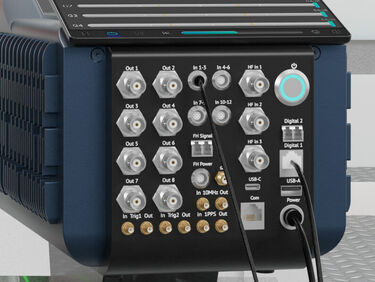
Optomet SMART Series: Easy integration of reference sensors
The systems of the SMART Series offer direct integration of reference sensors without additional hardware. Sensors are detected automatically and can be incorporated into the measurement workflow immediately.
Advantages:
- Directly connectable acceleration and force sensors as well as microphones
- Support for TEDS and IEPE sensors
- Synchronous logging of all channels
- Plug-and-play integration in SMART Lab software (signals visible immediately)
From 1D scanning to 3D scanning
Expandable through the modular Optomet SMART Series
The Optomet SMART Series is modular in design and can be expanded flexibly. A system initially used for one-dimensional scanning measurements can later be upgraded to a full 3D scanning vibrometer. The existing components remain part of the system and are simply complemented with additional devices and components from the SMART Series during an upgrade.
This modular approach makes it possible to start with a compact 1D system and gradually expand its functionality as new measurement tasks arise. In this way, the system grows with the requirements and remains adaptable in the long term.

"For more than two decades, Optomet has stood for precise vibration measurement. Our scanning laser vibrometers provide reliable data – from laboratory analysis to industrial quality control."
Tobias Schröder (M.Sc. Mechanical Engineering)
Head of Sales & Marketing
Typische Anwendungen in Forschung und Industrie
Laser-scanning vibrometers are used for full-field vibration analysis across a wide range of applications. They enable the investigation of complex structures, the determination of mode shapes and natural frequencies, and the analysis of vibrations under real operating conditions.
Typical applications:
- Modal analysis – Determination of natural frequencies, mode shapes, and damping values
- NVH investigations – Analysis of noise and vibration effects in vehicles and components
- Aerospace – Structural dynamic investigations on wings, fuselage sections, or engine components
- Mechanical engineering – Vibration analysis on machines, gearboxes, pumps, and rotating systems
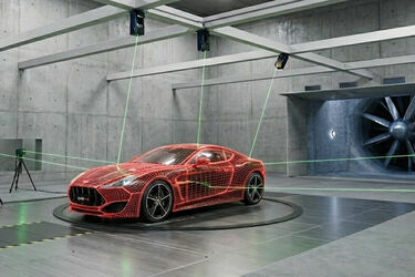
- Wind tunnel – In BMW’s new wind tunnel, Optomet laser Doppler vibrometers are used to capture vibrations under aerodynamic loads.


Laser-scanning vibrometers from Optomet
Optomet offers a range of laser-scanning vibrometers for different measurement requirements – from compact 1D systems to fully integrated 3D solutions. The devices differ in configuration, frequency range, and functional scope.
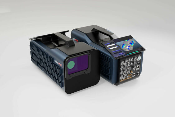
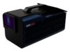
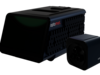
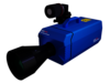
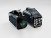
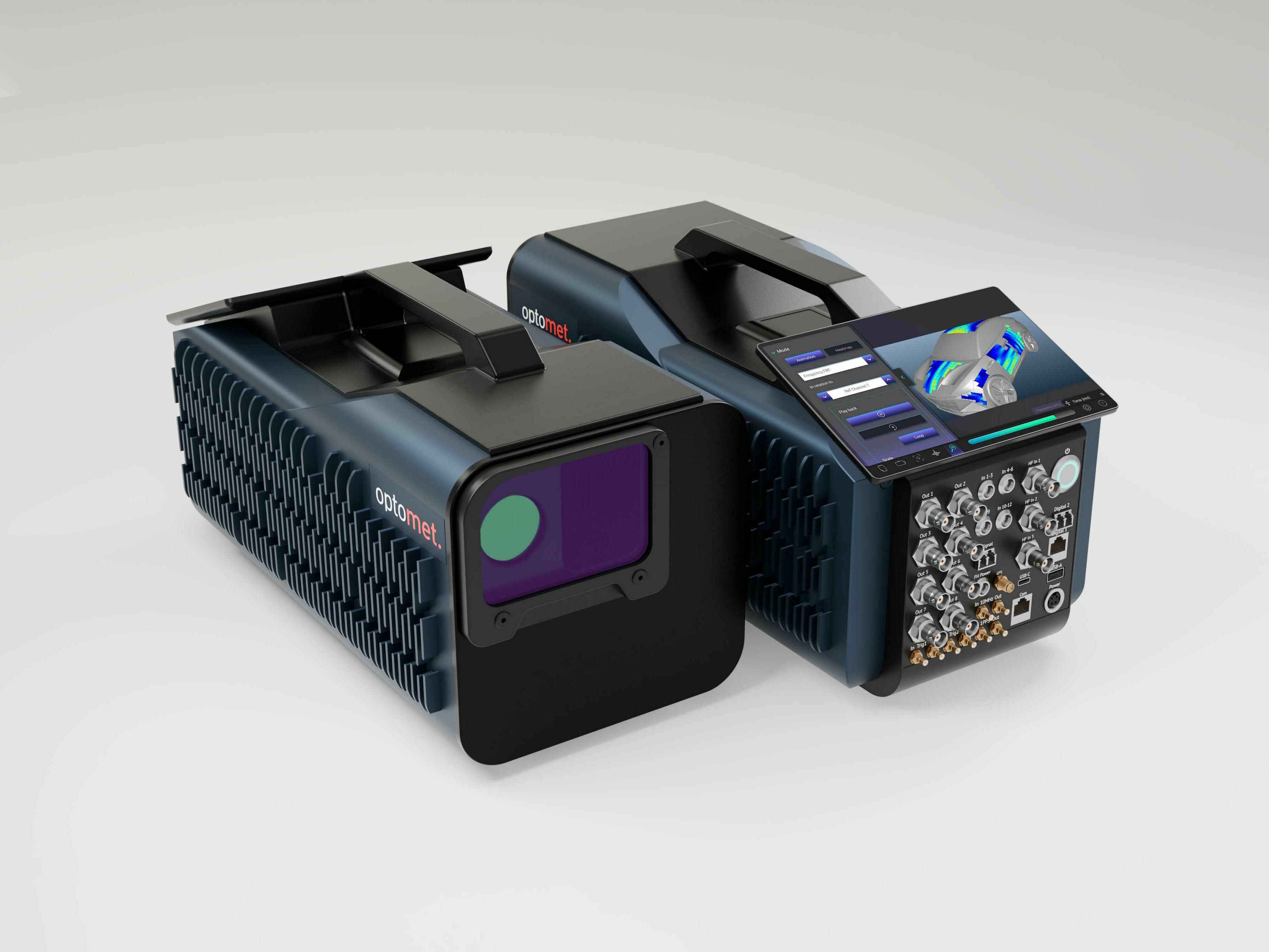
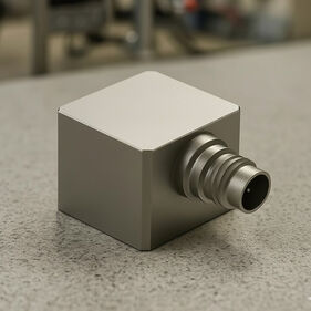
SMART Scan+
The SMART Scan+ is a digital laser-scanning vibrometer for full-field vibration measurements. The system combines an integrated camera with automated point scanning and is suitable for modal analyses, NVH investigations, and structural dynamics testing.
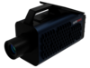
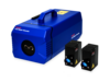
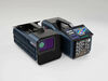
SMART 3D-Scan
The SMART 3D-Scan vibrometer extends the scanning method to include three-dimensional vibration analysis.
It captures all three vibration directions simultaneously for each measurement point: in-plane and out-of-plane measurements enable complete 3D mode shapes even for complex structures.“
Learn more about SMART 3D-Scan | SMART 3D-Scan datasheet (PDF)

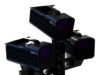
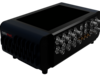
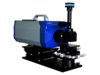
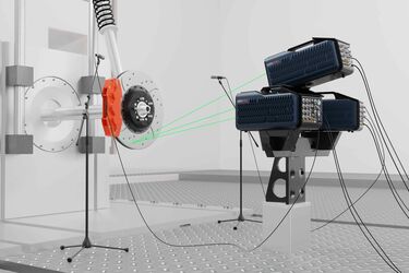
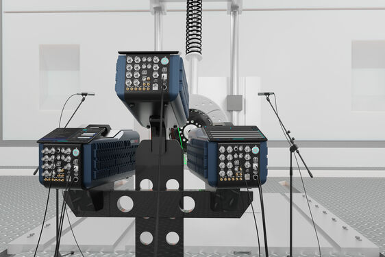
SMART Full Body
SMART Full Body is a flexible measurement system that allows multiple SMART Scan+ vibrometers to be positioned around the test object. This makes it possible to capture large structures from different perspectives. Alternatively, a single SMART Scan+ can be used, with the measurement data automatically combined into a full vibration shape using SMART Lab.
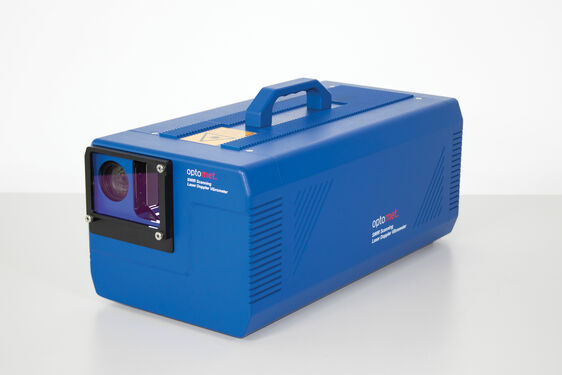
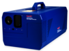
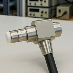
Scanning vibrometer (CLASSIC Series)
The Classic Scanning Vibrometer is a compact scanning system. In contrast to the SMART Series, it is less modular and is used as a fully configured device. The large optical aperture and the integrated video support enable stable measurements even on dark or rough surfaces as well as at larger working distances.
Learn more about the SWIR scanning vibrometer | Datasheet CLASSIC Scanning Vibrometer (PDF)
Scanning vibrometer in the validation process
The validation of FEM models is a key step in ensuring that a simulation accurately represents the real dynamic behavior of a component. Laser-scanning vibrometers provide full-field vibration data that can be directly compared with FEM results. Mode shapes, natural frequencies, and damping values are checked, and deviations between the model and reality are identified.
The validation process includes the following steps, among others:
- Comparison of simulation (FEM) with real measured vibration data
- Verification of mode shapes, natural frequencies, and damping
- Adjustment of boundary conditions, material parameters, and stiffnesses
- Ensuring that the real component reproduces the simulated behavior
- Identification and evaluation of deviations between the model and reality
Why is this comparison important?
Only a verified FEM model enables reliable predictions of structural behavior. By comparing simulated and measured data, model parameters can be specifically adjusted and optimized. This leads to faster development processes and reduces the number of required iterations.
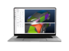
Optimal workflow with Optomet SMART Lab
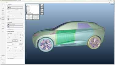
SMART Lab supports the entire validation process, as simulation and measurement are combined in a single consistent coordinate system. 3D FEM models can be imported directly, measurement points can be automatically mapped to FEM nodes, and deviations become visible immediately.
SMART Lab offers:
- Import of 3D FEM models (e.g., NASTRAN) directly into the software
- Measurement directly on FEM nodes through automatic assignment of scanning points
- Exact placement of all measurement points on simulation nodes without manual matching
- A consistent coordinate system for simulation and real measurement data
- Fast identification of deviations between simulation and measurement (modes, frequencies, damping)
Advantages of validation:
- Only a valid FEM model provides reliable predictions
- Optimization of the FEM model through comparison with real measurement data
- Shortened development times
- Fewer iteration cycles in the design process
Integration into automation and test-bench environments
Laser-scanning vibrometers can be easily integrated into existing test stands, automation environments, or measurement chains. Through open interfaces, all measurement data is available both digitally and analogically and can be processed directly by higher-level systems.
Interfaces and integration options:
- Ethernet interface for digital transmission of velocity, displacement, and acceleration data
- Analog output channels for direct integration into existing DAQ hardware
- Open control and data protocols for automated processes and external triggers
- Flexible operation in semi- or fully automated measurement systems
Thanks to the combination of digital and analog interfaces, the vibrometer can operate either as a standalone measurement system or as part of a fully automated setup.
FAQ: Laser-scanning vibrometers
In this section, you will find answers to typical questions about measurement duration, point density, surfaces, references, software, laser sources, and integration into existing measurement and automation environments.
A single-point vibrometer measures vibration at a single point along the laser axis.
A scanning vibrometer automatically directs the laser across many measurement points and generates a full-field vibration shape. This allows mode shapes, natural frequencies, and spatial vibration distributions to be visualized.
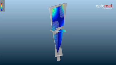
Yes. For three-dimensional vibration analysis, Optomet uses a system consisting of three scanning vibrometers working together as a 3D scanning unit. Each vibrometer measures vibration from its own direction. The three systems are time-synchronized, align their measurement points, and exchange essential control and reference signals during the measurement.
From the three velocity components recorded at each measurement point, the system calculates the complete motion in X, Y, and Z directions. This allows complex 3D mode shapes and spatial motion directions to be represented precisely.
Optomet scanning vibrometers operate with eye-safe laser sources.
The invisible SWIR measurement laser (1550 nm) is classified as Laser Class 1 (< 10 mW) and requires no safety goggles. Some systems can alternatively be operated with a visible HeNe measurement laser (632.8 nm), classified as Laser Class 2 (< 1 mW), also considered eye-safe. For alignment, a visible pilot laser is used, also Laser Class 2 (< 1 mW). All lasers are safe in normal operation and specified in the technical datasheets of each device.
Depending on the application, Optomet uses different laser sources. Standard systems use SWIR lasers (1550 nm), which offer high optical sensitivity and require no surface preparation. Alternatively, visible HeNe lasers (632.8 nm) may be used depending on the application area. The laser source is selected during the technical configuration.
Scanning vibrometers always measure the individual points sequentially. The laser beam automatically moves across the defined grid, and each point is recorded separately. Using a reference signal, the time-offset individual measurements are then brought into correct phase alignment, resulting in a complete vibration shape.
For Full Body Scans, multiple scanning vibrometers operate in parallel.
Each device still measures its points sequentially, but they cover different areas of the object simultaneously. In SMART Lab, all points are merged spatially and temporally.
- Single scanning vibrometer: points are measured sequentially.
- Full Body Scan (multiple vibrometers): several sequential scans run in parallel and are synchronized.
The excitation method depends on the measurement approach and the goal of the investigation. For defined, reproducible vibrations, active excitation sources such as a shaker, modal hammer, or piezo actuator are commonly used. In operational measurements, the structure can be excited by real influences such as engine operation, wind, or process forces.
Typical excitation methods:
- Modal hammer for impulse excitation
- Shaker for defined, frequency-variable, or broadband excitation
- Piezo actuators for high-frequency or local excitation
- Sound fields (e.g., loudspeakers) for acoustic excitation
- Real operating conditions when the behavior under load is to be analyzed
- Internal signal generator (in Optomet scanning vibrometers) as a defined, integrated excitation source
For scanning vibrometers, the software solutions SMART Lab and OptoSCAN offer complete integration of scanning grids, device control, and data analysis.
However, their use is not mandatory: all measurement data can also be output via digital or analog interfaces and processed in any external analysis environment.
Usage options:
- SMART Lab / OptoSCAN / OptoGUI for full control, visualization, and analysis
- External software (e.g., MATLAB, LabVIEW, Python, FEM tools, or custom solutions) via open data and control interfaces
- Analog or digital raw data output (e.g., velocity, acceleration, displacement) for direct downstream processing
This allows the vibrometer to be used both as a fully integrated measurement solution and flexibly as a data source within existing analysis or automation systems.
Scanning vibrometers can be integrated into automated test stands and existing measurement chains through open interfaces. Measurement data is available both digitally and analogically and can be transferred directly into external systems.
Interfaces and integration:
- Gigabit Ethernet for digital measurement data and control commands
- Analog outputs for velocity, acceleration, or displacement
- External triggers for synchronized measurement processes
- Open data formats for processing in custom systems
- Compatible with automated sequences, e.g., for test-bench or end-of-line applications
This allows the vibrometer to be used either as a standalone measurement system or as part of a fully automated setup.
The duration of a scanning measurement depends on several factors such as desired frequency resolution, number of measurement points, and the vibration frequencies being investigated. For a quick overview, the object can be scanned at up to 50 points per second.
The required number of measurement points depends on the spatial complexity of the modes being investigated. Higher frequencies have shorter wavelengths and more nodal lines, requiring a denser spatial sampling to capture the vibration shapes accurately.
SMART scanning vibrometers can record up to 512 × 512 measurement points across the defined measurement area. This allows even complex structures to be analyzed fully and with high resolution.
No. The SWIR lasers of Optomet laser-scanning vibrometers enable reliable measurement without reflector tape, even on dark or rough surfaces. The high sensitivity and strong return signal provide a stable, high signal-to-noise ratio even under challenging conditions.
The scanning vibrometer can be used across a wide range of distances. Depending on the setup and object size, the following working distances are possible:
- Up to 100 m distance for standard scanning applications – ideal for large structures or hard-to-access measurement objects.
- Minimum working distance from approx. 6.5 mm when measuring very small objects or fine details.
This allows the system to reliably cover both short-distance measurements in the micrometer range and long-distance measurements in industrial environments.
Yes. Optomet’s SMART Lab software supports the import of 3D models. Users can load their FEM geometries and place measurement points directly on FEM nodes. This makes it possible to precisely compare measurement data and simulation, enabling efficient validation and optimization of FEM models.
An Optomet laser-scanning vibrometer covers a very wide size range:
- Very small structures < 1 mm², e.g., MEMS components
- Large objects > 10 m², such as housings, machine parts, or large components
With the Optomet SMART Series, multiple scanning vibrometers can be synchronously networked, enabling measurements on entire vehicles or aircraft (“Full-body vibrometry”).
With a single device, frequencies from DC to 50 MHz can be detected – suitable for slow vibrations as well as for very high-frequency dynamic processes.
Related Terms & Knowledge
Laser Sources
Fundamentals of the laser types used in vibrometry – Helium-Neon, SWIR, and fiber-coupled systems.
Laser Doppler Vibrometry
Structure, operating principle, and application areas of Laser Doppler Vibrometry.
Vibration Measurement
Methods, measurement setup, and evaluation of vibration data in research and industry.
Doppler Effect
Physical principle of Laser Doppler Vibrometry – the basis for precise velocity measurement.
Signal Processing
Analysis of vibration data using FFT, frequency-domain evaluation, and real-time processing.
Downloads

Brochure SMART-Series (pdf)
Laser Vibrometry is getting SMART
One system, unlimited possibilities
Vibration measurement in research, development, and industry — Optomet offers the right solution for your application.
CallNow
Europe: 9:00am - 5:00pm (UTC+1)
Americas: 3:00am - 12:00pm (UTC-5)
Asia: 3:00pm - 0:00am (UTC+8)
CallBack